




























What Is An EMI Filter?
Quick Answer
An EMI filter is a network of inductors, capacitors, and resistors that blocks or shunts high-frequency noise while allowing the desired power or signal to pass. They come in two main flavors: power-line filters for AC/DC mains and signal-line filters for data, audio, and RF. The most common topology combines an inductor in series with X/Y safety capacitors in a π or T arrangement, providing both common-mode and differential-mode rejection.
EMI Filter Definition
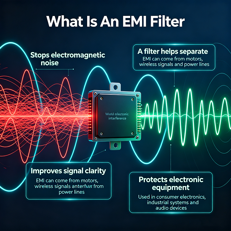
Formally, an EMI filter is a two-port network inserted between a noise source and a victim circuit that:
- Passes desired signals (DC power, AC mains, or data) with minimal loss.
- Attenuates unwanted RF energy on the line by a specified amount, typically expressed in dB.
- Provides defined impedance on both source and load sides for predictable filtering.
EMI filters target conducted noise — noise that travels along wires and cables rather than radiating through free space. Radiated noise, while related, requires different mitigation (shielding, layout, antennas).
Why EMI Filters Matter
Modern electronics switch at ever-higher frequencies. Microprocessors, motor drives, LED dimmers, and switching power supplies all generate fast edges that contain energy across a wide RF spectrum. Without filtering, this noise can:
- Fail regulatory tests (FCC Part 15, CE EN 55011/32, CISPR 22).
- Interfere with nearby equipment (radios, medical devices, instrumentation).
- Disturb the host product itself through conducted loops and ground bounce.
- Compromise safety systems in automotive, aerospace, and medical applications.
Common-Mode vs. Differential-Mode Noise
Common-Mode (CM) Noise
Noise that appears equally on both lines with respect to ground. Caused by fast switching, parasitic capacitance to chassis, and external fields. Suppressed by common-mode chokes and Y-capacitors.
Differential-Mode (DM) Noise
Noise that flows between the two lines (line-to-line). Caused by rectifier ripple, load transients, and switching harmonics. Suppressed by X-capacitors and differential inductors.
A good EMI filter addresses both modes. Most power-line filters include a common-mode choke (for CM), an X-capacitor (for DM), and Y-capacitors (for CM-to-ground).
How an EMI Filter Works
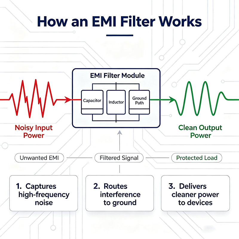
The core components do three things:
- Inductors block high-frequency current by presenting increasing impedance with frequency (Z = jωL).
- Capacitors shunt high-frequency voltage to ground or between lines by presenting decreasing impedance (Z = 1 / jωC).
- Resistors damp resonances and discharge X-capacitors for safety.
The combination is arranged into π (C-L-C), T (L-C-L), or L-section topologies depending on source and load impedances.
Key Components
| Component | Function | Placement |
|---|---|---|
| X-capacitor | Shunts differential-mode noise line-to-line | Across L and N |
| Y-capacitor | Shunts common-mode noise to ground | L/N to PE |
| Common-mode choke | Blocks common-mode current | Series in L and N |
| Differential inductor | Blocks differential-mode current | Series in one line |
| Bleeder resistor | Discharges X-capacitor for safety | Across X-capacitor |
| MOV / TVS | Suppresses voltage transients | Across mains |
| Ferrite bead | Adds high-frequency loss | Series in signal lines |
Types of EMI Filters
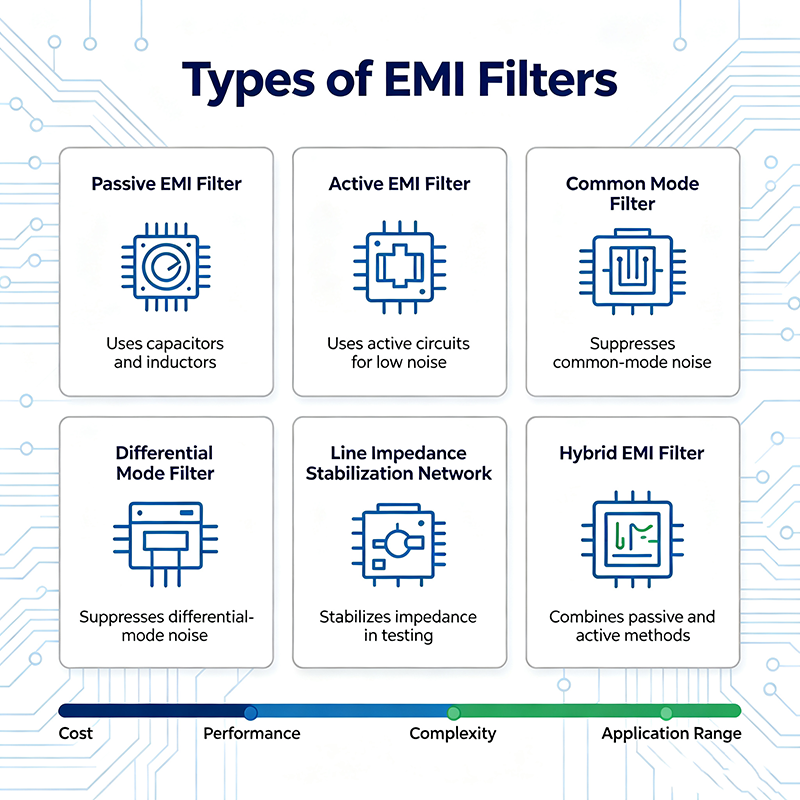
AC Power-Line Filter
Single-phase or three-phase filters for mains. Combined CM choke + X/Y caps + bleeder. Standard for IEC inlet, appliance, and industrial equipment.
DC Power-Line Filter
Filters noise on DC power rails in vehicles, telecom, and battery-driven systems. Typically LC lowpass with high current rating.
Ferrite Bead Filter
Small ferrite slipped over a wire or PCB trace. Cheap, single-component high-frequency loss. Common on USB, HDMI, and signal cables.
Common-Mode Choke for Data
Used on Ethernet, USB, HDMI, and CAN bus. Blocks common-mode noise without affecting differential data signals.
Three-Phase Industrial Filter
Designed for 3-phase industrial equipment, motor drives, and inverters. Handles high current and high dV/dt from IGBTs.
Military / Aerospace Filter
Qualified to MIL-STD-461 and DO-160. Built to survive shock, vibration, and temperature extremes.
Medical-Grade Filter
Low leakage current to patient-connected circuits per IEC 60601-1. Smaller Y-capacitors reduce ground current.
PCB Mount Filter Module
Compact integrated modules with through-hole or SMT pins. Saves board space, optimized for specific frequencies.
Key Specifications
| Specification | Meaning |
|---|---|
| Insertion Loss | Attenuation (dB) vs. frequency, both CM and DM |
| Rated Voltage | Maximum continuous operating voltage (AC/DC) |
| Rated Current | Maximum continuous current at rated temperature |
| Leakage Current | Current through Y-capacitors to PE, important for medical |
| Hipot Rating | Withstand voltage between line and ground |
| Operating Temperature | Thermal limits for the device |
| Approvals | UL, CE, TÜV, CSA safety certifications |
| Impedance (Source/Load) | Designed for 50 Ω or specific line impedance |
Insertion Loss Explained
Insertion loss (IL) is the ratio of voltage across the load with the filter inserted versus without it, expressed in dB. A 40 dB IL means the noise at that frequency is reduced by a factor of 100.
Most datasheets plot IL assuming a 50 Ω source and 50 Ω load. Real-world line impedances vary wildly, so actual performance may differ significantly. Always measure in the final system.
Filtering Topologies
- L-section: simplest — one series inductor and one shunt capacitor. Low cost, modest performance.
- π-section (Pi): capacitor-inductor-capacitor. Higher attenuation than L-section.
- T-section: inductor-capacitor-inductor. Best for low-impedance sources and loads.
- Multi-stage: cascaded π or T sections for very high attenuation.
Real-World Applications
- Consumer electronics: TVs, computers, kitchen appliances to meet FCC/CE.
- Industrial: motor drives, inverters, CNC machines, factory automation.
- Automotive: EVs, infotainment, ADAS — must meet CISPR 25 / ISO 11452.
- Medical: MRI, patient monitors, infusion pumps — IEC 60601-1 leakage limits.
- Aerospace & defense: MIL-STD-461, DO-160 qualified filters.
- Renewable energy: solar inverters, wind turbines, battery storage systems.
- Telecom & data centers: server PSUs, base-station power, network switches.
Common Mistakes
- Filter placed too far from connector: the wiring between filter and connector becomes an antenna.
- Wrong CM/DM design: filter optimized for CM noise but real noise is DM (or vice versa).
- Insufficient Y-capacitor rating: medical and aircraft applications have tight leakage limits.
- Ignoring source impedance: insertion loss is specified for 50 Ω but the actual source may be 5 Ω or 500 Ω.
- Forgetting bleeder resistor: safety hazard if X-capacitor remains charged after unplugging.
- Ground loop issues: filter ground must be a low-inductance connection to chassis.
How to Choose the Right EMI Filter
- Identify the noise source: switching frequency, harmonics, transient amplitudes.
- Determine the regulatory standard you must meet (FCC Class A/B, CE, CISPR).
- Match rated voltage and current to your application.
- Check insertion loss curves for the frequencies of concern.
- Verify leakage current is within medical or safety limits.
- Confirm mechanical fit, mounting style, and connector type.
- Validate performance in the final product using a conducted-emissions test setup.
EMI Filter vs. Surge Protector vs. TVS
| Device | Targets | Response | Cost |
|---|---|---|---|
| EMI Filter | Continuous RF noise | Passive attenuation | Low – moderate |
| MOV | Voltage transients | Clamps at threshold | Low |
| TVS Diode | Fast voltage spikes | Sub-ns clamping | Low |
| Gas Discharge Tube | Lightning surges | Crowbars at high voltage | Moderate |
EMI filters address continuous noise; surge protectors address transient events. The two are complementary — a robust product uses both.
Key Takeaways
- An EMI filter is a passive LC network that attenuates conducted RF noise.
- Common-mode and differential-mode noise require different filter elements.
- Power-line filters protect against conducted emissions; signal-line filters protect sensitive signals.
- Insertion loss curves assume 50 Ω — always validate in your real system.
- Place filters close to connectors and bond grounds with low inductance.
Frequently Asked Questions
What is an EMI filter?
An EMI filter is a passive electronic circuit made of inductors, capacitors, and sometimes resistors that suppresses conducted electromagnetic interference on power or signal lines while allowing the desired power or data to pass.
What is the difference between common-mode and differential-mode noise?
Common-mode noise appears equally on both lines with respect to ground. Differential-mode noise flows between the two lines. EMI filters use different components to address each mode.
Where should an EMI filter be placed?
As close as possible to the I/O connector or noise source, with a low-inductance ground connection to chassis. Placing it far away lets the wiring between act as an unintended antenna.
Are EMI filters required by law?
Not strictly required, but most regulatory standards (FCC Part 15, CE EN 55011/32, CISPR 22/25) set emission limits that almost always require EMI filtering to pass.
What is leakage current in an EMI filter?
Leakage current is the small AC current that flows through the Y-capacitors from line or neutral to protective earth. Medical and aviation standards set strict limits on leakage current for safety.
About the Author — MeiXun Team
Chief Engineer Wang
High-tech Enterprise, Feifeng Talent
Chief Engineer Wang graduated with a master's degree in high-power microwave from the Institute of Electronics, University of Chinese Academy of Sciences.
View Full Profile- RF Switch Circuit Diagram
- RF Switch
- Ohm's Law
- dBm to Watt
- mW to dBm
- Wavelength to Frequency
- RF Connector
- SMA Connector
- RF Switch Module
- RF Coupler
- RF PIN Switch
- Microwave Coaxial Switch
- PIN Switch
- Coaxial RF Switch
- Waveguide Switch
- Microwave Switch
- Low Noise Amplifier
- PIN Diode Switch
- Coaxial Switch
- RF Microwave Switch
- SPST Switch