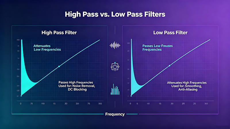
A lowpass filter is one of the most fundamental building blocks in electronics and signal processing. It allows signals below a chosen cutoff frequency to pass through while attenuating higher frequencies, making it indispensable for cleaning noise, preventing aliasing, protecting speakers, and shaping the frequency response of audio, RF, and data-acquisition systems.
Quick Answer
A lowpass filter (LPF) passes frequencies below its cutoff frequency (fc) and attenuates frequencies above it. By removing unwanted high-frequency content — noise, harmonics, interference, or aliasing artifacts — the lowpass filter directly improves signal-to-noise ratio, dynamic range, and overall signal quality.
Lowpass Filter Definition
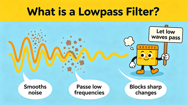
A lowpass filter is a two-port network whose magnitude response is shaped to favor low-frequency components. The frequency at which output power drops to one-half (−3 dB) of the passband value is called the cutoff frequency, denoted fc or f−3dB.
Mathematically, an ideal lowpass filter has a rectangular response: unity gain for f < fc and infinite attenuation for f > fc. Practical filters approximate this response with a gradual transition region called the roll-off, characterized by its order and topology.
Why "Enhances Signal Quality"?
"Signal quality" describes how faithfully a signal represents the information it carries. Several metrics define quality:
-
Signal-to-Noise Ratio (SNR): the level of desired signal versus unwanted noise.
-
Total Harmonic Distortion (THD): the amount of harmonic content added by the system.
-
Spurious-free Dynamic Range (SFDR): the usable range above the noise floor.
-
Bit Error Rate (BER): the error rate in digital communications.
A well-designed lowpass filter improves each of these by removing high-frequency noise and spurious tones that would otherwise corrupt the signal. The result is cleaner audio, sharper images, more reliable data, and safer operation of downstream electronics.
How a Lowpass Filter Works
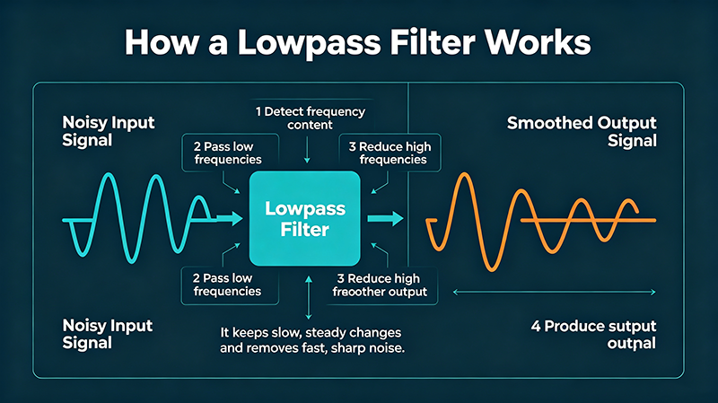
1. Receive Input Signal
→
2. Split by Frequency
→
3. Pass Low Frequencies
→
4. Attenuate High Frequencies
At its most basic level, a lowpass filter uses a frequency-dependent impedance element — usually a capacitor — that diverts high-frequency energy away from the output while allowing low-frequency energy to flow through.
RC Lowpass Filter (First-Order)
The simplest analog implementation is a series resistor R followed by a shunt capacitor C to ground. The output taken across the capacitor rolls off high frequencies because the capacitor's impedance decreases as frequency rises.
The cutoff frequency is:
fc = 1 / (2πRC)
Below fc the signal passes with little loss; above fc the magnitude drops at −20 dB per decade.
RL and LC Lowpass Filters
-
RL lowpass: series inductor with shunt resistor — useful when capacitors are impractical (e.g., high-current power filtering).
-
LC lowpass: series inductor with shunt capacitor — common in RF, audio crossovers, and switching power-supply output filters.
-
π-filter and T-filter: cascaded L and C sections for steeper roll-off and higher stopband attenuation.
Active Lowpass Filters
When gain, isolation, or steeper roll-off is required, an op-amp is added to form an active lowpass filter. Popular topologies include:
-
Sallen-Key — simple, good for second-order Butterworth and Bessel responses.
-
Multiple Feedback (MFB) — inverting topology with high gain accuracy.
-
State-variable — independent control of frequency, Q, and gain.
-
Switched-capacitor — clock-tunable, used in audio codecs.
Types of Lowpass Filters
Passive
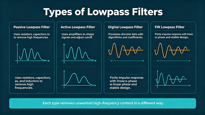
RC Lowpass Filter
A resistor and capacitor form the simplest LPF. Cheap, easy, and perfect for gentle noise reduction or coupling stages.
Passive
LC Lowpass Filter
Inductor + capacitor sections deliver low loss and high current capability — standard in RF and power-electronics filtering.
Active
Op-Amp Lowpass Filter
Provides gain, isolation, and steep roll-off. Sallen-Key and MFB topologies are widely used in audio and instrumentation.
Topology
Butterworth
Maximally flat passband with no ripple. The most popular general-purpose LPF response.
Topology
Chebyshev
Steeper roll-off than Butterworth at the cost of passband ripple. Useful when sharp cutoff is critical.
Topology
Bessel
Best phase linearity. Ideal for preserving pulse shapes and digital waveforms.
Topology
Elliptic (Cauer)
Steepest possible transition with equal ripple in passband and stopband. Demands more components.
Digital
Digital Lowpass Filter
Implemented in software using FIR or IIR coefficients — flexible, programmable, and free of component tolerances.
Key Specifications
|
Specification
|
Description
|
|
Cutoff Frequency (fc)
|
−3 dB point separating passband and stopband
|
|
Passband Ripple
|
Allowed gain variation in the passband (0 dB for Butterworth)
|
|
Roll-off Rate
|
Steepness of attenuation in dB/decade (20 dB/dec per order)
|
|
Stopband Attenuation
|
How strongly unwanted frequencies are rejected
|
|
Phase Response
|
How the filter delays different frequency components
|
|
Group Delay
|
Time delay of the envelope; critical for pulse and data signals
|
|
Input / Output Impedance
|
Must be matched to source and load to avoid affecting fc
|
|
Insertion Loss
|
Power lost in the passband (especially in passive LC filters)
|
How a Lowpass Filter Enhances Signal Quality
1. Removes High-Frequency Noise
Broadband thermal noise, switching supply ripple, and RF interference all sit above the useful signal band. A lowpass filter cleans the spectrum, raising SNR and reducing jitter in digital systems.
2. Prevents Aliasing
According to the Nyquist-Shannon sampling theorem, signals must be band-limited below half the sampling rate before analog-to-digital conversion. A lowpass anti-aliasing filter placed before the ADC removes content that would otherwise fold back into the audible or measurable band and corrupt the result.
3. Reduces Harmonic Distortion
Non-linear stages generate harmonics at multiples of the fundamental. A well-placed lowpass filter removes these harmonics before they reach the output, lowering THD and improving spectral purity.
4. Smooths PWM and Switching Outputs
In class-D amplifiers and switching regulators, the output is a high-frequency PWM square wave. An LC lowpass filter reconstructs the original audio or DC waveform, reducing EMI and improving efficiency.
5. Protects Downstream Stages
High-frequency energy can saturate amplifiers, overheat speakers, or violate regulatory emission limits. A lowpass filter acts as a guard, ensuring only the intended band reaches sensitive stages.
Pro Tip: Place the lowpass filter as close as possible to the noise source. The earlier unwanted high-frequency energy is removed, the less it can couple into other parts of the system through ground loops or capacitive crosstalk.
Real-World Applications
Audio Engineering
-
Subwoofer low-pass crossovers (typically 80–120 Hz) keep deep bass away from midrange drivers.
-
Anti-aliasing filters before ADC inputs in recording interfaces.
-
Reconstruction filters after DACs to remove update-rate images.
-
Noise-shaping loops in sigma-delta converters use lowpass filters to push quantization noise out of band.
Radio Frequency (RF)
-
Receiver front-end lowpass filters remove out-of-band blockers and image frequencies.
-
Transmitter output lowpass filters suppress harmonics to meet FCC/ETSI emission masks.
-
Software-defined radio uses digital lowpass filters for channel selection.
Image Processing
-
Gaussian blur is mathematically a 2-D lowpass filter used for noise reduction and pre-processing.
-
Bilateral filters combine lowpass smoothing with edge preservation.
-
Multi-scale analysis decomposes images into lowpass and highpass bands (e.g., Laplacian pyramid).
Power Electronics
-
LC output filters in switch-mode power supplies smooth PWM into clean DC.
-
EMI input filters combine common-mode chokes with X/Y capacitors acting as lowpass networks.
-
Motor-drive lowpass filters reduce winding insulation stress from high dV/dt edges.
Data Acquisition
-
Anti-aliasing lowpass filters before ADCs protect sample integrity.
-
Digital lowpass filters (moving average, Butterworth IIR, FIR) clean up sensor data.
-
Lock-in amplifiers use lowpass filters after phase-sensitive detection.
Choosing the Right Lowpass Filter
-
Determine the highest frequency you need to preserve — set fc comfortably above it.
-
Decide how much stopband attenuation you need — this dictates filter order.
-
Choose a topology that matches your passband requirements (Butterworth = flat, Bessel = linear phase, Chebyshev = steepest).
-
Verify impedance compatibility between source, filter, and load.
-
Simulate the response with tools such as TI FilterPro, Analog Devices Filter Wizard, or Python SciPy.
-
Measure the actual hardware with a swept sine or network analyzer.
Common Mistakes
-
Setting fc too low: removes useful signal content and causes audible dullness.
-
Forgetting load impedance: changes the effective R and shifts the cutoff frequency.
-
Over-ordering the filter: more stages add phase delay and ringing; order should match the requirement.
-
Ignoring input common-mode voltage: op-amp-based LPFs have limited input ranges.
-
Mixing analog and digital grounds poorly: noise couples into the filter from digital return currents.
Key Takeaways
-
A lowpass filter passes signals below fc and attenuates higher ones.
-
It enhances signal quality by removing noise, harmonics, aliasing, and interference.
-
Filter order and topology determine how steep the roll-off is and how linear the phase remains.
-
RC, LC, and op-amp implementations cover everything from gentle coupling to precision anti-aliasing.
-
Always simulate and measure — never trust a calculated cutoff alone.
Frequently Asked Questions
What does a lowpass filter do?
A lowpass filter allows frequencies below its cutoff frequency to pass through while attenuating higher frequencies. This removes noise, harmonics, and unwanted high-frequency content from a signal.
How does a lowpass filter improve signal quality?
It suppresses broadband noise, removes harmonics and aliasing, smooths switching waveforms, and protects downstream electronics. The result is higher SNR, lower THD, and cleaner output spectra.
What is the cutoff frequency of a lowpass filter?
The cutoff frequency fc is the −3 dB point where output power falls to one-half of the passband value. It is the boundary between the passband and the transition region.
What is the difference between first-order and second-order lowpass filters?
A first-order LPF attenuates at 20 dB/decade above fc. A second-order LPF attenuates at 40 dB/decade, providing a steeper transition and better stopband rejection, but with slightly more phase shift.
Can a lowpass filter remove 50/60 Hz hum?
No — 50/60 Hz hum is below most lowpass cutoffs and therefore passes through. To remove mains hum you need a highpass filter, a notch filter at the mains frequency, or proper shielding and grounding.