




























How to Choose a Proper Fixed Attenuator
A fixed attenuator is a passive device that reduces signal amplitude by a specific amount without distorting the waveform. It is an essential component in RF and microwave systems, used for level matching, impedance stabilization, and protecting sensitive receivers. However, with so many options on the market, selecting the right fixed attenuator requires careful evaluation of electrical, mechanical, and thermal parameters.
This article provides a step-by-step methodology for choosing a proper fixed attenuator that delivers reliable performance across your entire operating band.
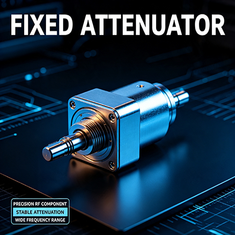
1. Understand the Function of a Fixed Attenuator
A fixed attenuator uses a resistive network to reduce signal power while presenting a constant impedance to the source and load. Unlike variable attenuators, the attenuation level is fixed and cannot be adjusted. Common applications include:
- Matching signal levels between amplifier stages
- Protecting spectrum analyzers and receivers from overdrive
- Improving VSWR by adding loss between mismatched components
- Calibrating test setups and extending dynamic range
- Reducing power to meet regulatory or safety limits
Because the attenuator sits directly in the signal path, its performance directly impacts system bandwidth, noise figure, and overall signal quality.
2. Key Specifications to Evaluate
Attenuation Value (dB)
The attenuation value determines how much the signal is reduced. Common values range from 0 dB to 60 dB. To select the correct value, calculate the required reduction in power from your source to the desired output level. Remember that a 3 dB attenuator halves the power, a 6 dB attenuator reduces power to one-quarter, and a 10 dB attenuator reduces power to one-tenth. Always choose a value that leaves sufficient margin for signal-to-noise ratio and dynamic range.
Frequency Range
The frequency range is the band over which the attenuator maintains its specified attenuation and return loss. Low-cost attenuators may work from DC to 3 GHz, while precision models reach 40 GHz or higher. Check that the attenuator's frequency range fully covers your operating band, including harmonics and out-of-band signals that may be present. At higher frequencies, parasitic elements cause attenuation variation, so choose a model with flat response over your critical frequencies.
Impedance
Most RF systems use 50 Ω impedance, but 75 Ω is also common in cable television and video applications. The attenuator must have the same characteristic impedance as the system. Using a 50 Ω attenuator in a 75 Ω system (or vice versa) will cause reflections and signal degradation, often with unpredictable results.
Power Handling Capability
Power handling specifies how much average power the attenuator can safely dissipate without overheating or failing. It is usually expressed in watts (W). Exceeding the power rating can cause resistance drift, connector damage, or even fire. Always select an attenuator with a power rating at least 1.5 to 2 times the maximum continuous power you expect. For pulsed applications, also consider peak power handling.
VSWR / Return Loss
VSWR (Voltage Standing Wave Ratio) or return loss indicates how well the attenuator is impedance-matched. A low VSWR (high return loss) ensures minimal reflections and maximum power transfer. For most precision applications, a VSWR of 1.20:1 or better (return loss ≥ 20 dB) is recommended. Attenuators with poor VSWR can cause measurement errors and system ripple.
Connector Type and Gender
Connectors must be compatible with your cables, instruments, and DUT interfaces. Common connector types include SMA, N, BNC, TNC, 2.92 mm (K), 2.4 mm, and 1.85 mm (V). SMA is the workhorse for low-power, broadband applications up to 18 GHz. N connectors are preferred for high-power or low-frequency use. Precision connectors are used in millimeter-wave bands. Also pay attention to gender: male-to-female, female-to-female, or male-to-male configurations are available.
Accuracy and Flatness
Accuracy refers to how close the actual attenuation is to the nominal value at a given frequency. Flatness describes the variation in attenuation across the frequency band. High-quality attenuators maintain an accuracy of ±0.3 dB or better, while precision metrology-grade units can achieve ±0.1 dB. Check the datasheet curves to ensure the attenuation is flat over your operating band.
Temperature Stability
In environments with wide temperature variations, the resistive elements may shift, changing the attenuation value. Look for attenuators with specified temperature coefficients if your system operates outdoors or in uncontrolled conditions. Most commercial units perform well from -55°C to +125°C, but verify the datasheet.
3. Step-by-Step Selection Process
- Determine the required attenuation value. Calculate the necessary power reduction in dB.
- Identify the operating frequency range. Note the lowest and highest frequencies of interest.
- Check the system impedance. Confirm 50 Ω or 75 Ω compatibility.
- Estimate the maximum average and peak power. Add safety margin (1.5x to 2x) for power rating.
- Select the appropriate connector type and gender. Match the existing cables and equipment.
- Review VSWR, accuracy, and flatness. Verify that the attenuator meets your signal integrity budget.
- Consider mechanical and environmental requirements. Check size, weight, and temperature range if applicable.
- Compare datasheets from multiple manufacturers. Look for S-parameter data and real measurement curves.
4. Quick Reference Selection Table
| Parameter | What to Look For | Why It Matters |
|---|---|---|
| Attenuation Value | Matches required reduction with margin | Avoids under/over attenuation |
| Frequency Range | Covers full signal band | Prevents excessive loss or mismatch at band edges |
| Impedance | Matches system (50 Ω or 75 Ω) | Eliminates reflections and mismatch loss |
| Power Handling | 1.5x to 2x max power | Prevents thermal damage and failure |
| VSWR | ≤ 1.20:1 (return loss ≥ 20 dB) | Maintains signal integrity and system accuracy |
| Connector | Compatible with existing interfaces | Ensures mechanical and electrical connectivity |
| Accuracy / Flatness | ±0.3 dB or better | Guarantees predictable attenuation |
- Attenuation value provides the required signal reduction
- Frequency range fully covers the operating band
- Impedance matches the system (50 Ω or 75 Ω)
- Power rating exceeds maximum expected power with margin
- VSWR / return loss meets system requirements
- Connector type and gender are physically compatible
- Attenuation accuracy and flatness are acceptable over temperature range
- Mechanical size and environmental rating fit the application
5. Common Mistakes to Avoid
- Ignoring power derating at high temperatures – check the manufacturer's derating curve.
- Selecting an attenuator based only on attenuation value without checking VSWR.
- Using a 50 Ω attenuator in a 75 Ω system (or vice versa).
- Exceeding the maximum input power, even for short durations.
- Overlooking connector gender configuration, causing extra adapters and additional loss.
- Failing to verify low-frequency performance when using DC-coupled systems.
Conclusion
Selecting the right fixed attenuator requires more than simply choosing a dB value. A proper selection ensures flat frequency response, low VSWR, adequate power handling, and reliable operation over the full environmental range. By following the steps and guidelines in this article, you can confidently choose an attenuator that preserves signal integrity, protects your equipment, and contributes to the long-term reliability of your RF system.
Always refer to the manufacturer's datasheet for detailed performance data, and when in doubt, consult with application engineers to verify your choice.
About the Author — MeiXun Team
Chief Engineer Wang
High-tech Enterprise, Feifeng Talent
Chief Engineer Wang graduated with a master's degree in high-power microwave from the Institute of Electronics, University of Chinese Academy of Sciences.
View Full Profile- RF Switch Circuit Diagram
- RF Switch
- Ohm's Law
- dBm to Watt
- mW to dBm
- Wavelength to Frequency
- RF Connector
- SMA Connector
- RF Switch Module
- RF Coupler
- RF PIN Switch
- Microwave Coaxial Switch
- PIN Switch
- Coaxial RF Switch
- Waveguide Switch
- Microwave Switch
- Low Noise Amplifier
- PIN Diode Switch
- Coaxial Switch
- RF Microwave Switch
- SPST Switch