




























Electronic Attenuator: Types, Working Principle & Applications
Quick Answer
An electronic attenuator uses a controllable solid-state element — typically a PIN diode, GaAs MESFET, or MMIC variable-gain block — to absorb or divert a portion of the input RF signal. A control voltage or digital word selects the attenuation level. Common forms are digital step attenuators, voltage-variable analog attenuators, and programmable multi-state attenuators for ATE.
What Is an Electronic Attenuator?
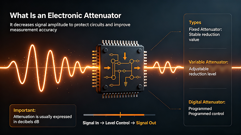
An electronic attenuator is a two-port device that adjusts the gain (or loss) between its input and output using an electrical control signal. Unlike a passive fixed attenuator that has a single attenuation value, an electronic attenuator can vary its attenuation in real time.
Electronic attenuators fall into two broad categories:
- Analog (continuous) attenuators: attenuation varies continuously with a control voltage or current.
- Digital (stepped) attenuators: attenuation is selected from a set of discrete steps by a digital word.
How an Electronic Attenuator Works
Electronic Attenuator — Basic Principle
A control signal (analog voltage or digital word) adjusts the attenuator cell, which absorbs or diverts a portion of the input signal, leaving the rest to pass to the output.
Common Implementations
1. PIN Diode Attenuator
A PIN diode is biased with a DC current that controls its RF impedance. By placing PIN diodes in shunt or series, the attenuation is set by the bias current. PIN attenuators handle high power and offer broadband performance.
2. GaAs MESFET / pHEMT Attenuator
A GaAs FET in its resistive region acts as a voltage-controlled resistor. FET attenuators are common in MMIC form, providing low distortion and good power handling up to a few GHz.
3. MMIC Variable Gain Block
Integrated MMIC attenuators combine the active device, matching, and bias in a single chip. They are widely used in cellular transceivers and ATE systems for digitally controlled attenuation.
4. Digital Step Attenuator
Built from cascaded fixed-attenuator stages (e.g., 1, 2, 4, 8, 16, 32 dB). A digital control word selects which stages are activated. Common steps are 0.5 dB, 1 dB, or 5 dB.
5. Analog Voltage-Variable Attenuator
A continuous attenuator whose attenuation is set by a DC control voltage. Used in AGC loops, leveling circuits, and automatic test equipment.
Key Specifications
| Specification | Meaning |
|---|---|
| Frequency Range | Operating band |
| Attenuation Range | Min / max attenuation in dB |
| Resolution | Smallest step (digital) or linearity (analog) |
| Insertion Loss | Loss at minimum attenuation setting |
| VSWR | Match at all attenuation states |
| Power Handling | Max CW / pulsed input |
| Switching Speed | Time to change state |
| Linearity (IP3 / P1dB) | Distortion performance |
| Phase Variation | Phase shift between states |
| Control Interface | Analog voltage, parallel, SPI, I²C |
Types of Electronic Attenuators
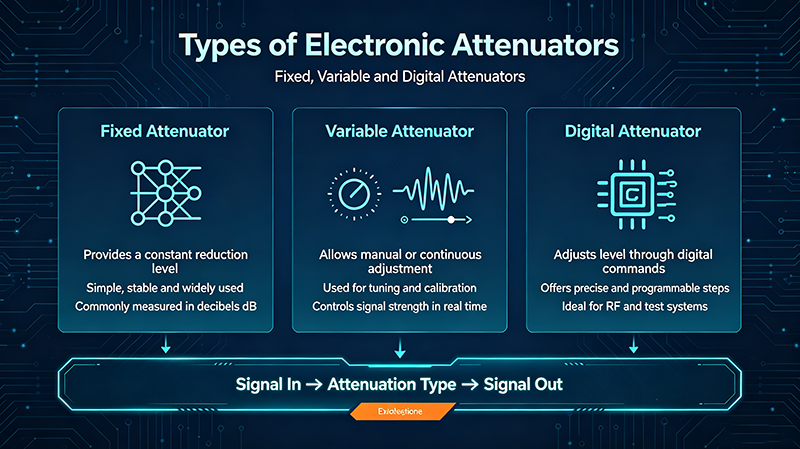
Digital Step Attenuator
Cascaded binary-weighted cells controlled by a digital word. Standard for ATE, beamforming, and cellular base stations.
Voltage-Variable Attenuator
Continuous attenuation set by a DC control voltage. Used in AGC loops and leveling circuits.
PIN Diode Attenuator
Handles higher RF power than GaAs MESFETs. Used in cellular infrastructure and high-power systems.
GaAs MESFET Attenuator
Low distortion, broadband. Standard for instrumentation, test, and wireless transceivers.
MMIC Variable Attenuator
Fully integrated chip. Saves PCB area and provides repeatable performance in volume production.
Multi-State Programmable Attenuator
Self-contained module with internal DAC, addressable via USB / Ethernet / SPI / GPIB. Ideal for ATE.
Digital Step Attenuator Topologies
| Topology | Attenuation | Steps | Use |
|---|---|---|---|
| Binary-Weighted | 0 – 31 dB | 1 dB | Standard 5-bit DSA |
| Thermometer | 0 – 31 dB | 1 dB (31 cells) | Low glitch, high linearity |
| Multi-Decade | 0 – 95 dB | 0.25 dB + coarse stages | Fine resolution + wide range |
| Direct-Switch | 0 – N × L dB | Programmable | Custom applications |
Design Considerations
- Insertion loss: at minimum attenuation, loss should be as low as possible (typically < 2 dB).
- VSWR flatness: VSWR should remain stable across all attenuation states — many attenuators have poor match at mid-range.
- Phase consistency: for beamforming and phased arrays, phase must be repeatable across attenuation states.
- Settling time: switching speed affects ATE throughput and AGC loop bandwidth.
- Glitch-free transitions: critical for AGC loops; some designs include special transitions to avoid pops.
- Distortion: P1dB and IP3 must be high enough for the system linearity requirement.
Real-World Applications
1. Automatic Gain Control (AGC)
Receiver AGC loops use a voltage-variable attenuator to keep the signal level constant despite input power variations.
2. Cellular Base Stations
Digital step attenuators balance transmit power, compensate for temperature drift, and support multi-user MIMO.
3. Phased-Array Radar & Beamforming
Each antenna element has an attenuator that sets amplitude tapers, while phase shifters handle beam steering.
4. Automatic Test Equipment (ATE)
Programmable attenuators set precise test levels for receivers, transceivers, and baseband ICs.
5. RF Signal Generators
Built-in attenuators provide fine amplitude control across wide dynamic ranges (often 120 dB or more).
6. Power-Leveling Loops
Closed-loop leveling in test systems uses an attenuator to maintain a constant output despite source drift.
7. Cable & Path Equalization
Attenuators compensate for varying cable loss between components in distributed antenna systems (DAS).
Integration Tips
- Place the attenuator close to where level control is needed.
- Use controlled-impedance traces with proper 50 Ω termination.
- Provide clean DC supplies with local decoupling.
- Shield digital control lines from RF traces.
- Read the datasheet for control-voltage range and interface type.
Common Mistakes
- Exceeding input power: PIN and GaAs attenuators have absolute maximum ratings.
- Wrong control logic: 3.3 V logic applied to a 5 V part (or vice versa) can damage the device.
- Ignoring switching transients: glitches can disrupt AGC loops and ATE tests.
- Skipping calibration: attenuation accuracy drifts with frequency, temperature, and aging.
- Wrong impedance: 75 Ω attenuators used in 50 Ω systems cause reflections and poor match.
Verification & Testing
- Measure S-parameters at every attenuation state.
- Verify attenuation accuracy against expected values across the band.
- Measure switching speed and any glitches with a fast oscilloscope.
- Test linearity (P1dB, IP3) at maximum and minimum attenuation.
- Thermal-cycle and verify attenuation drift.
Key Takeaways
- Electronic attenuators adjust RF level using an electrical control signal.
- PIN, GaAs, and MMIC are the dominant technologies.
- Digital step attenuators offer precise, repeatable levels; analog attenuators offer continuous control.
- VSWR flatness, phase variation, and switching speed are key specs.
- Electronic attenuators are essential in AGC, ATE, beamforming, and leveling systems.
Frequently Asked Questions
What is an electronic attenuator?
An electronic attenuator is an RF component that reduces signal level by a controlled amount using a voltage or digital word. It has no moving parts.
Digital or analog attenuator — which is better?
Digital attenuators offer precise, repeatable settings and easy microprocessor control. Analog attenuators offer continuous adjustment and are ideal for AGC loops.
What is a PIN diode attenuator used for?
PIN diode attenuators handle higher RF power than GaAs MESFETs. They are common in cellular infrastructure, broadcast, and high-power test systems.
What is the difference between an attenuator and a gain block?
An attenuator only reduces signal level; a gain block amplifies. Variable-gain amplifiers combine both — gain or attenuation can be applied.
How fast can electronic attenuators switch?
PIN and GaAs MESFET attenuators can switch in tens of nanoseconds. MMIC variable attenuators typically switch in tens of nanoseconds to a few microseconds.
About the Author — MeiXun Team
Chief Engineer Wang
High-tech Enterprise, Feifeng Talent
Chief Engineer Wang graduated with a master's degree in high-power microwave from the Institute of Electronics, University of Chinese Academy of Sciences.
View Full Profile- RF Switch Circuit Diagram
- RF Switch
- Ohm's Law
- dBm to Watt
- mW to dBm
- Wavelength to Frequency
- RF Connector
- SMA Connector
- RF Switch Module
- RF Coupler
- RF PIN Switch
- Microwave Coaxial Switch
- PIN Switch
- Coaxial RF Switch
- Waveguide Switch
- Microwave Switch
- Low Noise Amplifier
- PIN Diode Switch
- Coaxial Switch
- RF Microwave Switch
- SPST Switch