




























A low-pass filter (LPF) is one of the most widely used circuits in RF, microwave, audio, telecommunications, instrumentation, and electronic systems. It allows signals below a selected cutoff frequency to pass while attenuating higher-frequency components.
Understanding the low-pass filter formula is essential when designing filters, selecting RF and microwave components, calculating cutoff frequency, or evaluating insertion loss and signal attenuation. The most fundamental relationship for a first-order RC low-pass filter is fc = 1/(2πRC), while LC and higher-order filters use different equations and design methods.
What Is a Low-Pass Filter?
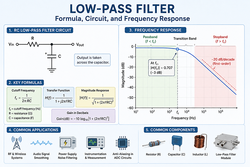
A low-pass filter is a frequency-selective circuit designed to pass frequencies below a specified cutoff frequency and reduce frequencies above that point. The cutoff frequency marks the transition between the passband and stopband.
Low-pass filters can be implemented using resistors, capacitors, inductors, transmission lines, or combinations of these components. In practical RF and microwave systems, low-pass filters are commonly constructed using LC networks, microstrip structures, coaxial components, cavity structures, or other distributed-element technologies.
The Basic Low-Pass Filter Formula
For a simple first-order RC low-pass filter, the cutoff frequency is calculated using the following formula:
This is the most commonly referenced low-pass filter formula. It shows that the cutoff frequency depends directly on the resistance and capacitance values.
Increasing either R or C increases the RC time constant and therefore decreases the cutoff frequency. Conversely, reducing R or C increases the cutoff frequency.
Understanding the Variables
| Symbol | Parameter | Unit | Function |
|---|---|---|---|
| fc | Cutoff frequency | Hz | Defines the approximate boundary between the passband and transition region. |
| R | Resistance | Ω | Determines the RC time constant together with the capacitor. |
| C | Capacitance | F | Provides increasing attenuation as frequency rises. |
| π | Pi | Dimensionless | Constant approximately equal to 3.14159. |
How the RC Low-Pass Filter Works
A basic RC low-pass filter consists of a resistor connected in series with the input and a capacitor connected from the output node to ground. The output voltage is measured across the capacitor.
At low frequencies, the capacitor has relatively high impedance, so most of the input signal appears at the output. As frequency increases, the capacitor impedance decreases, allowing more of the high-frequency signal to flow toward ground.
The impedance of a capacitor is described by:
Because capacitive reactance decreases as frequency increases, high-frequency signals experience greater attenuation in an RC low-pass network.
Low-Pass Filter Transfer Function
The frequency response of a first-order RC low-pass filter can be expressed using its transfer function:
The magnitude of the transfer function is:
This equation describes how the output amplitude changes as the input frequency increases.
Response at the Cutoff Frequency
At the cutoff frequency, the magnitude of the output is approximately 0.707 of the input voltage:
The −3 dB point is conventionally used to define the cutoff frequency of a first-order low-pass filter.
Low-Pass Filter Cutoff Frequency Formula
The cutoff frequency can be calculated from the RC values using:
The formula can also be rearranged to calculate the required resistor or capacitor:
These rearranged equations are particularly useful when designing a low-pass filter for a specific cutoff frequency.
Low-Pass Filter Formula Example
Consider an RC low-pass filter with a resistor of 1 kΩ and a capacitor of 100 nF.
C = 100 × 10⁻⁹ F
Substituting these values into the cutoff frequency equation:
Therefore, the approximate cutoff frequency is 1.59 kHz.
Low-Pass Filter Gain in Decibels
Engineers frequently express filter attenuation and gain in decibels rather than as a voltage ratio. The magnitude response of a first-order RC low-pass filter can be converted to decibels using:
Combining this with the RC transfer function gives:
At frequencies significantly below cutoff, attenuation is small. At the cutoff frequency, attenuation is approximately 3 dB. Above cutoff, attenuation increases progressively.
What Is the Roll-Off Rate of a Low-Pass Filter?
A first-order low-pass filter has a theoretical roll-off rate of approximately −20 dB per decade above its cutoff frequency.
This means that when the frequency increases by a factor of ten, the attenuation increases by approximately 20 dB in the ideal asymptotic region.
| Filter Order | Typical Roll-Off | Characteristics |
|---|---|---|
| 1st order | −20 dB/decade | Simple design and gradual attenuation |
| 2nd order | −40 dB/decade | Greater high-frequency rejection |
| 3rd order | −60 dB/decade | Sharper transition from passband to stopband |
| 4th order | −80 dB/decade | Strong stopband attenuation |
Higher-order filters are commonly used when a sharper transition is required between desired and unwanted frequency ranges.
LC Low-Pass Filter Formula
RC filters are convenient for low-frequency applications, but LC low-pass filters are often preferred in RF and microwave applications because inductors and capacitors can provide better impedance matching and lower insertion loss in suitable frequency ranges.
A simplified LC resonant frequency relationship is:
This equation is fundamental to many LC filter designs. However, the actual cutoff frequency of a complete LC low-pass filter depends on the filter topology, element values, termination impedance, filter order, and response type.
Common Types of Low-Pass Filters
1. RC Low-Pass Filter
The RC low-pass filter is simple, inexpensive, and widely used for signal conditioning, sensor interfaces, audio circuits, analog electronics, and noise reduction.
2. RL Low-Pass Filter
An RL low-pass filter uses a resistor and inductor. Its cutoff frequency for a basic first-order topology can be expressed as:
3. LC Low-Pass Filter
LC filters use inductors and capacitors to provide frequency-selective behavior with potentially lower resistive losses than simple RC networks. They are widely used in power supplies, RF circuits, impedance matching networks, and RF front ends.
4. RLC Low-Pass Filter
RLC filters combine resistance, inductance, and capacitance. They provide greater flexibility in controlling bandwidth, damping, resonance, and frequency response.
5. Active Low-Pass Filter
Active low-pass filters use operational amplifiers or other active devices together with resistors and capacitors. They can provide gain as well as filtering and are commonly used in analog signal processing.
Butterworth Low-Pass Filter Formula
A Butterworth filter is designed to provide a maximally flat magnitude response in the passband. For a normalized Butterworth low-pass filter, the squared magnitude response can be represented as:
The corresponding angular cutoff frequency is:
Butterworth filters are frequently selected when a smooth passband response is more important than achieving the steepest possible transition for a given filter order.
Chebyshev Low-Pass Filters
Chebyshev filters provide a sharper transition between the passband and stopband than Butterworth filters of the same order, but they introduce passband ripple in the conventional Type I design.
A Chebyshev response can therefore be useful when stopband attenuation must be achieved close to the desired passband edge and some passband ripple is acceptable.
Low-Pass Filter Formula for RF and Microwave Applications
In RF and microwave engineering, low-pass filter design becomes more complex because parasitic effects, transmission-line behavior, impedance matching, connector performance, and component Q-factor can significantly affect the actual response.
Important specifications for an RF low-pass filter include:
- Cutoff frequency
- Passband insertion loss
- Stopband attenuation
- Return loss
- VSWR
- Power handling capability
- Impedance, commonly 50 Ω in RF systems
- Operating frequency range
- Connector type
- Temperature stability
For a practical microwave filter, simply applying the basic RC formula is generally insufficient. Engineers typically use filter synthesis techniques, electromagnetic simulation, circuit simulation, or measured S-parameters to optimize the design.
Low-Pass Filter Transfer Function and S-Parameters
RF engineers often evaluate low-pass filters using S-parameters. The most important parameters are S21 and S11.
- S21: Indicates forward transmission and is commonly used to evaluate insertion loss.
- S11: Indicates input reflection and is used to evaluate impedance matching.
A well-designed RF low-pass filter should provide low insertion loss within the passband and strong attenuation at unwanted frequencies while maintaining an acceptable return loss.
How to Calculate a Low-Pass Filter Step by Step
- Define the desired cutoff frequency.
- Determine the system impedance and operating frequency range.
- Select an appropriate filter topology.
- Choose the desired filter response, such as Butterworth or Chebyshev.
- Calculate the initial component values.
- Consider component tolerances and parasitic effects.
- Simulate the frequency response.
- Build or select the filter.
- Measure insertion loss and return loss.
- Compare the measured performance with the design requirements.
Factors That Affect Real-World Low-Pass Filter Performance
Component Tolerance
Real capacitors and inductors have manufacturing tolerances. A component specified as 100 nF, for example, may not have exactly that value. These deviations shift the actual cutoff frequency.
Parasitic Capacitance and Inductance
PCB traces, component leads, packages, vias, connectors, and mounting structures introduce parasitic capacitance and inductance. These effects become increasingly important as frequency rises.
Component Q-Factor
Inductor and capacitor quality factors influence filter insertion loss. Higher-Q components generally enable lower loss and better filter performance within their appropriate operating frequency ranges.
Source and Load Impedance
The filter response depends on the source and load conditions. A filter designed for a 50 Ω RF system may behave differently when connected to a substantially different impedance.
PCB Layout
PCB layout is particularly important for high-frequency filters. Long traces, poor grounding, insufficient via placement, and unintended coupling can alter the expected frequency response.
Low-Pass Filter vs High-Pass Filter
A low-pass filter and a high-pass filter perform opposite frequency-selective functions.
| Characteristic | Low-Pass Filter | High-Pass Filter |
|---|---|---|
| Passes | Frequencies below cutoff | Frequencies above cutoff |
| Attenuates | Higher frequencies | Lower frequencies |
| Typical use | Noise reduction, RF filtering, signal smoothing | DC blocking, coupling, high-frequency signal selection |
| Basic RC formula | fc = 1/(2πRC) | fc = 1/(2πRC) |
Although the basic RC cutoff relationship is the same in magnitude, the circuit topology determines whether the network behaves as a low-pass or high-pass filter.
Applications of Low-Pass Filters
Low-pass filters are used across a wide range of electronic and RF systems, including:
- RF receiver front ends
- Wireless communication systems
- Radar systems
- Satellite communication equipment
- 5G and cellular infrastructure
- Signal conditioning circuits
- Audio electronics
- Power supply noise suppression
- Analog-to-digital converter anti-aliasing circuits
- EMI and electromagnetic interference suppression
- Test and measurement equipment
- RF power amplifier systems
Low-Pass Filter Design Example for RF Systems
Suppose an RF system needs to pass signals below a defined frequency while suppressing higher-order harmonics generated by an active RF device. The designer must consider more than the nominal cutoff frequency.
The design process should include the required passband, stopband attenuation, impedance, insertion loss, return loss, power level, and physical implementation. For example, a 50 Ω RF low-pass filter may be synthesized using normalized prototype coefficients and then scaled to the required cutoff frequency and impedance.
After the initial design, electromagnetic and circuit simulations can be used to account for PCB traces, component models, connectors, and enclosure effects. A vector network analyzer can then be used to measure S11 and S21 and verify the actual filter performance.
Common Mistakes When Using the Low-Pass Filter Formula
1. Using Incorrect Units
One of the most common calculation errors is mixing kΩ with Ω or nF with F without converting units. Always convert component values to their correct SI units before applying the formula.
2. Treating Cutoff as a Hard Boundary
A low-pass filter does not suddenly stop transmitting at the cutoff frequency. The transition is gradual, and the exact attenuation depends on the filter order and response.
3. Ignoring Source and Load Effects
The simple RC equation assumes an idealized circuit. Actual source and load impedances can change the effective resistance and therefore shift the cutoff frequency.
4. Ignoring Parasitics at High Frequencies
At RF and microwave frequencies, component parasitics can become a significant part of the circuit. The theoretical formula should therefore be treated as the starting point rather than the final answer.
5. Selecting a Filter Only by Cutoff Frequency
A filter with the correct cutoff frequency may still fail the application if its insertion loss, stopband rejection, return loss, power rating, or physical interface does not meet system requirements.
How to Choose the Right Low-Pass Filter
When selecting a commercial low-pass filter, engineers should evaluate the complete electrical and mechanical specification rather than focusing only on the cutoff frequency.
| Specification | Why It Matters |
|---|---|
| Cutoff frequency | Determines the beginning of the filter transition region. |
| Passband insertion loss | Determines how much desired signal power is lost. |
| Stopband rejection | Determines how effectively unwanted frequencies are suppressed. |
| Return loss | Indicates how well the filter is impedance matched. |
| VSWR | Provides another measure of impedance matching quality. |
| Power handling | Ensures reliable operation at the intended RF power level. |
| Operating temperature | Determines whether performance remains stable under environmental conditions. |
| Connector/interface | Ensures mechanical and electrical compatibility with the system. |
Frequently Asked Questions About Low-Pass Filter Formulas
For a first-order RC low-pass filter, the cutoff frequency is fc = 1/(2πRC).
For a first-order low-pass filter, the −3 dB frequency is the cutoff frequency. At this point, the output voltage magnitude is approximately 70.7% of the passband value.
Rearrange the RC cutoff equation as C = 1/(2πfcR). Insert the desired cutoff frequency and selected resistance value to calculate the required capacitance.
Yes. Increasing the filter order generally increases the stopband roll-off rate, allowing the filter to provide stronger attenuation over a smaller frequency range.
RC filters are simple and cost-effective and are widely used at lower frequencies. LC filters can provide lower insertion loss and are particularly useful in RF, microwave, and power applications when properly designed.
The basic formula is useful for understanding the underlying concept, but high-frequency microwave filter design normally requires impedance-controlled networks, accurate component or distributed-element models, electromagnetic simulation, and measured S-parameter verification.
Conclusion
The low-pass filter formula provides the foundation for understanding and designing frequency-selective circuits. For a first-order RC low-pass filter, the key relationship is fc = 1/(2πRC). This equation allows engineers to calculate cutoff frequency and determine suitable resistor and capacitor values.
However, professional RF and microwave filter design requires consideration of additional parameters, including impedance matching, insertion loss, stopband attenuation, filter order, component Q-factor, parasitic effects, power handling, PCB layout, and operating frequency.
Whether the application involves RF communication, radar, satellite systems, 5G equipment, test instrumentation, or general electronics, understanding the mathematical principles behind low-pass filters is an important step toward achieving reliable signal filtering and system performance.