




























Troubleshooting RF Microwave Switch Failures: Coaxial and PIN Diode Switch Issues
RF microwave switches play a critical role in modern communication systems, radar platforms, satellite networks, wireless test equipment, aerospace electronics, and defense applications. They control signal routing while maintaining low insertion loss, high isolation, and excellent repeatability. However, even high-quality RF switches can experience performance degradation over time due to electrical stress, mechanical wear, environmental conditions, or improper operation.
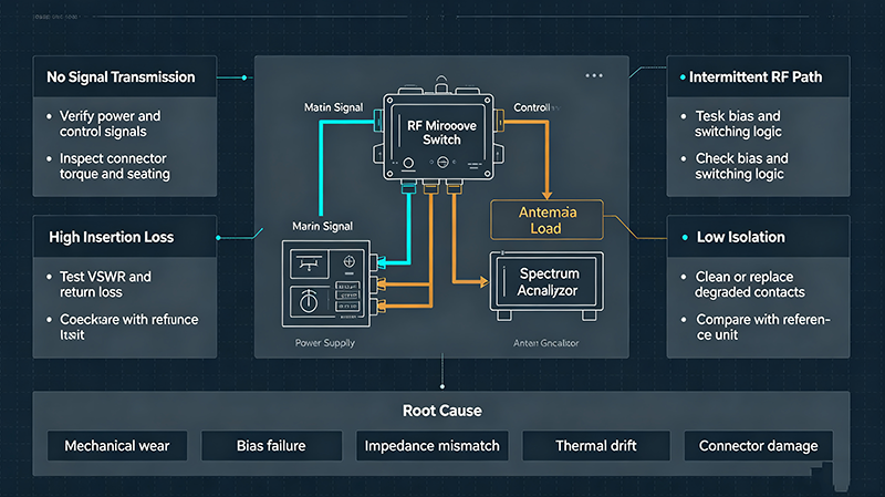
Understanding how to troubleshoot RF microwave switch failures can significantly reduce system downtime, lower maintenance costs, and improve long-term reliability. This guide explores the most common failure modes of coaxial RF switches and PIN diode switches, explains diagnostic procedures, and provides practical solutions for restoring optimal performance.
Understanding RF Microwave Switches
An RF microwave switch selectively routes RF signals between multiple signal paths while minimizing signal loss and interference. Depending on the application, switches may be mechanical or solid-state.
- Coaxial RF Switches use mechanical contacts to physically connect transmission paths.
- PIN Diode Switches use semiconductor PIN diodes controlled by bias current to electronically switch RF signals.
Each technology has unique advantages, operating characteristics, and failure mechanisms.
Common Symptoms of RF Microwave Switch Failures
Before troubleshooting, engineers should identify the symptoms that indicate switch malfunction.
| Symptom | Possible Cause |
|---|---|
| High insertion loss | Worn contacts, damaged connectors, contamination, diode degradation |
| Poor isolation | Contact wear, failed PIN diode, control circuit issues |
| High VSWR | Connector damage, impedance mismatch, mechanical deformation |
| Intermittent switching | Loose connections, unstable bias voltage, relay wear |
| Switch fails to actuate | Power supply failure, relay malfunction, driver circuit fault |
| Signal distortion | Nonlinear diode behavior, excessive RF power, damaged transmission path |
Troubleshooting Coaxial RF Switch Failures
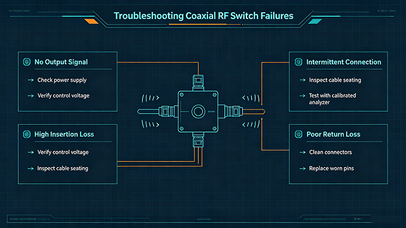
1. Mechanical Contact Wear
Mechanical RF switches rely on precision metal contacts that gradually wear after thousands or millions of switching cycles.
Typical symptoms include:
- Increasing insertion loss
- Reduced isolation
- Intermittent signal transmission
- Unstable measurement results
Inspect switching cycle history and compare measured RF performance against manufacturer specifications.
2. Connector Damage
Damaged SMA, N-type, 2.92 mm, or 3.5 mm connectors are among the most common causes of RF degradation.
Check for:
- Bent center conductors
- Damaged threads
- Loose connectors
- Over-tightened interfaces
- Surface contamination
Always use calibrated torque wrenches during installation.
3. Relay Failure
Electromechanical RF switches use relays or motors for actuation. Relay failure may result from:
- Coil burnout
- Mechanical fatigue
- Insufficient drive voltage
- Control board malfunction
Verify operating voltage and monitor relay response using an oscilloscope or multimeter.
4. Environmental Contamination
Dust, moisture, oxidation, and corrosive environments accelerate degradation.
Signs include:
- Corrosion on contacts
- Higher insertion loss
- Reduced repeatability
- Random switching failures
Store RF switches in clean, humidity-controlled environments whenever possible.
Troubleshooting PIN Diode RF Switch Issues
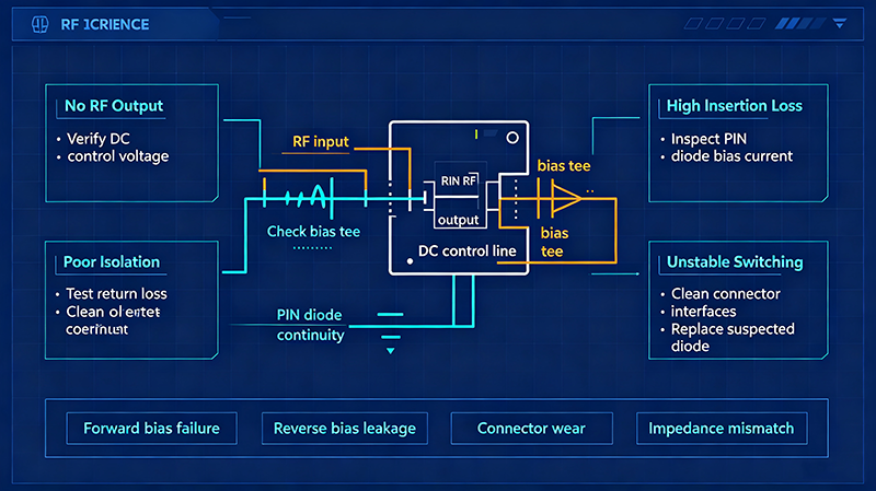
1. Incorrect Bias Voltage
PIN diode switches depend on precise forward and reverse bias control. Improper bias causes incomplete switching.
Measure:
- Forward current
- Reverse voltage
- Driver output waveform
- Control timing
Any deviation from specifications may affect isolation or insertion loss.
2. Diode Burnout from Excessive RF Power
PIN diodes can be permanently damaged by excessive RF power or voltage spikes.
Symptoms include:
- Permanent high insertion loss
- Poor isolation
- Complete signal blockage
- Thermal damage
Verify that transmitted RF power remains within rated operating limits.
3. Driver Circuit Failure
The PIN diode itself may remain functional while the driver circuitry fails.
Inspect:
- Control signals
- Current drivers
- Power regulators
- Logic interfaces
- Timing circuits
4. Thermal Stress
Repeated exposure to elevated temperatures accelerates semiconductor aging.
Use thermal imaging to identify hotspots and ensure adequate cooling in high-power systems.
Essential RF Switch Diagnostic Procedures
Measure Insertion Loss
Use a calibrated Vector Network Analyzer (VNA) to measure insertion loss across the operating frequency range.
Unexpected increases often indicate internal degradation.
Measure Isolation
Isolation testing reveals leakage between unused ports.
Reduced isolation typically points to worn contacts or damaged PIN diodes.
Check Return Loss and VSWR
Poor return loss indicates impedance mismatch caused by connector damage, mechanical wear, or internal failures.
Verify Control Signals
Use an oscilloscope to confirm:
- Voltage levels
- Current levels
- Switch timing
- Signal integrity
Perform Visual Inspection
Inspect the switch for:
- Loose hardware
- Burn marks
- Cracked housings
- Corrosion
- Damaged connectors
Preventive Maintenance Best Practices
- Keep RF connectors clean and protected with dust caps.
- Avoid exceeding rated RF power levels.
- Use proper connector torque tools.
- Monitor insertion loss periodically.
- Verify control voltage before operation.
- Operate within specified temperature limits.
- Schedule preventive inspections based on switching cycles.
- Replace worn mechanical switches before catastrophic failure occurs.
Coaxial vs. PIN Diode Switch Failure Comparison
| Feature | Coaxial Switch | PIN Diode Switch |
|---|---|---|
| Primary Failure Mode | Mechanical wear | Semiconductor degradation |
| Expected Lifetime | Limited by switching cycles | Limited by thermal and electrical stress |
| Switching Speed | Milliseconds | Nanoseconds to microseconds |
| Maintenance Requirement | Moderate | Low |
| Power Handling | Very High | Moderate |
| Typical Failure Indicator | Contact resistance increases | Bias or diode failure |
When Should You Replace an RF Microwave Switch?
Replacement is generally recommended when one or more of the following conditions exist:
- Insertion loss exceeds manufacturer specifications.
- Isolation cannot be restored through maintenance.
- Mechanical contacts have reached rated life.
- PIN diodes exhibit irreversible electrical damage.
- Connector interfaces cannot be repaired safely.
- Repair costs exceed replacement value.
Frequently Asked Questions (FAQ)
What is the most common cause of RF microwave switch failure?
Mechanical wear in coaxial switches and excessive electrical or thermal stress in PIN diode switches are the most common causes of failure.
How can insertion loss be measured accurately?
A calibrated Vector Network Analyzer (VNA) provides the most accurate measurement of insertion loss across the operating frequency range.
Can connector damage affect switch performance?
Yes. Damaged or contaminated connectors frequently increase insertion loss, worsen VSWR, and reduce overall RF system performance.
How often should RF switches be inspected?
Inspection intervals depend on switching frequency, operating environment, and application criticality. High-duty-cycle systems often require periodic RF performance verification and connector inspection.
Conclusion
Reliable RF microwave switch performance is essential for maintaining signal integrity in communications, aerospace, military, satellite, and laboratory applications. By understanding the distinct failure mechanisms of coaxial switches and PIN diode switches, engineers can quickly identify faults, minimize downtime, and extend equipment lifespan.
Routine testing using a Vector Network Analyzer, careful inspection of connectors and control circuits, proper environmental protection, and preventive maintenance all contribute to long-term system reliability. Whether troubleshooting mechanical contact wear or diagnosing semiconductor bias issues, a systematic approach ensures accurate fault isolation and optimal RF performance.
About the Author — MeiXun Team
Chief Engineer Wang
High-tech Enterprise, Feifeng Talent
Chief Engineer Wang graduated with a master's degree in high-power microwave from the Institute of Electronics, University of Chinese Academy of Sciences.
View Full Profile- RF Switch Circuit Diagram
- RF Switch
- Ohm's Law
- dBm to Watt
- mW to dBm
- Wavelength to Frequency
- RF Connector
- SMA Connector
- RF Switch Module
- RF Coupler
- RF PIN Switch
- Microwave Coaxial Switch
- PIN Switch
- Coaxial RF Switch
- Waveguide Switch
- Microwave Switch
- Low Noise Amplifier
- PIN Diode Switch
- Coaxial Switch
- RF Microwave Switch
- SPST Switch