MeiXun (Wuxi) Communication Technology Co.,Ltd
About Us
Db design (Shanghai)/MEIXUN (Wuxi) is a quality manufacturer of RF/Microwave components. Company established in Shanghai in 2012. Due to the enlargement of production line, we moved to Wuxi city in 2019.
Company Positioning: Deeply cultivate the microwave device field and strive to be a leader.
Market Policy: Enhance the brand value of customers with high-quality products and services.
Market Strategy: Same quality + better price + better service + independent controllability.
-
30%
R & D Design Team
-
10%
Management Team
-
50%
Production Team
-
10%
Marketing Team
High-tech Enterprise, Feifeng Talent
Technical Background
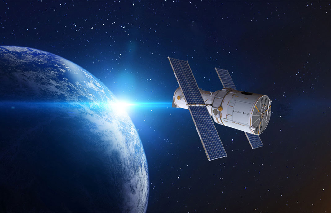
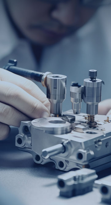
Chief Engineer Wang graduated with a master's degree in high-power microwave from the Institute of Electronics, University of Chinese Academy of Sciences. In the same year, he joined CETC 40/41 for work and study. He has been committed to the design and development of microwave switches for a long time. He has applied for 27 patents as the first inventor in the microwave switch field, with 6 authorized invention patents and 14 utility model patents. The products he developed cover various application platforms such as civilian testing, vehicle-mounted, shipborne, airborne, and missile-borne.
Quality Control
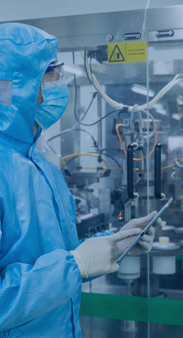
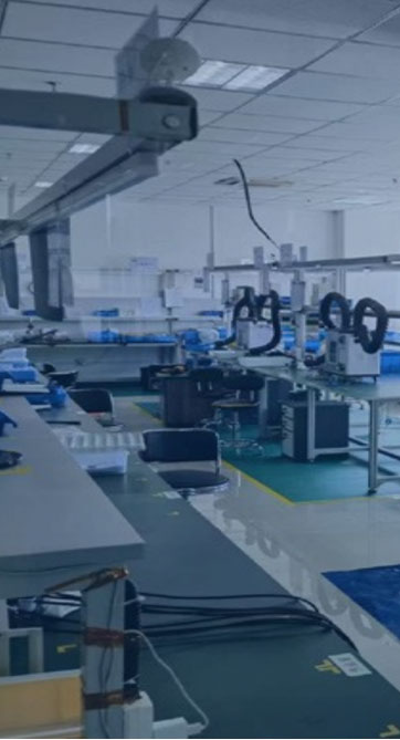
Production Line Control
• Fixed personnel, fixed positions + full production process traceability.
• Self-inspection on the production line + full-time inspection.
• Periodic inspection + outgoing inspection to ensure the reliable quality of materials
used inside the
devices.
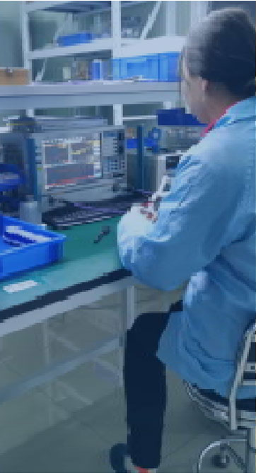
Strict Inspection
Intermodulation test, microwave test, life test, stability test, coating inspection, high-temperature aging, thermal shock.
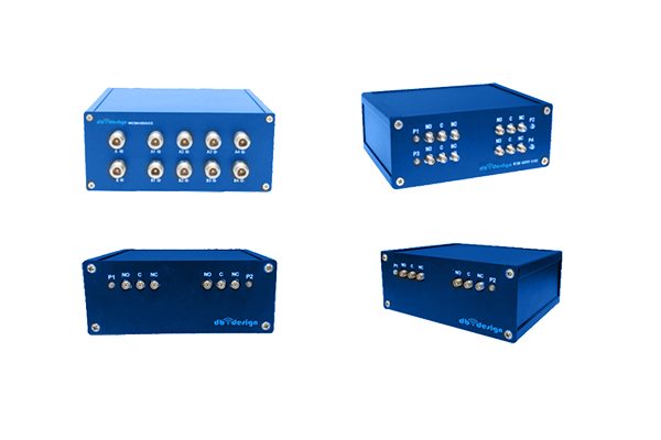
Product Service Center

Coaxial Switches
● Wide frequency range, up to 67GHz.
● Long service life and high transmission power.
● Low standing wave ratio, high isolation, low insertion loss, repeatability ≤ 0.05dB.
● Rich varieties, including SPDT, DPDT, SP4T, SP6T, SP10T, etc.