What are the steps to troubleshoot a coaxial switch
-
1 Verify System Configuration and Connections
-
Check power supply (e.g., DC 5V ±10%) and ground continuity.
-
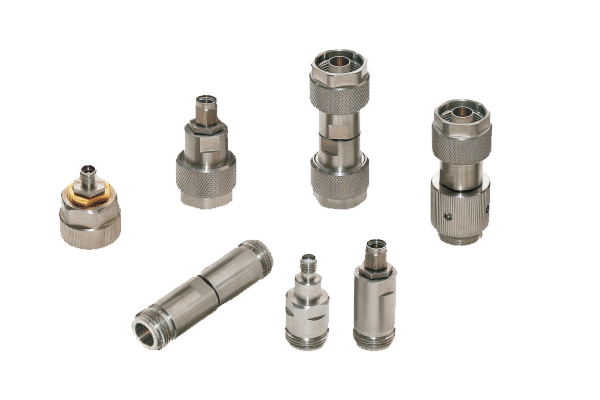
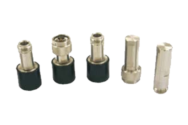
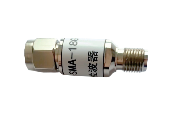
Inspect coaxial cables for physical damage (bent connectors, shield corrosion) and ensure tight mating with torque wrenches for precision connectors (e.g., SMA/N-type).
-
Validate control signals (TTL/GPIO) for remote operation: test voltage levels, pulse timing, and logic states with an oscilloscope.
-
2 Perform Basic Signal Tests
-
Insertion Loss: Compare measured loss (e.g., >0.5dB at 1GHz) against datasheet. Elevated loss indicates dirty contacts, loose connections, or degraded dielectrics.
-
Isolation: Test crosstalk between unused ports (e.g., < -30dB). Poor isolation suggests arcing, contact wear, or misalignment.
-
Return Loss: Measure reflection coefficient (e.g., < -15dB). High VSWR (>1.5:1) indicates impedance mismatches.
-
3 Inspect Mechanical Components
-
Visual Check: Examine connectors for oxidation, debris, or misalignment. For electromechanical switches, check for worn gears, loose springs, or damaged actuators.
-
Switching Mechanism: Manually operate the switch (if safe) to assess smoothness. Sticky/noisy operation may indicate lubricant degradation or mechanical fatigue.
-
Contact Resistance: Measure with micro-ohmmeter (<5mΩ for low-loss switches). High resistance indicates corrosion, pitting, or insufficient contact pressure.
-
4 Evaluate Environmental Factors
-
Test temperature/humidity within rated range (e.g., -40°C to 85°C). Thermal cycling may loosen connections or degrade seals.
-
Simulate vibration/shock with a shaker table. Loose components (e.g., solder joints) may fail under stress.
-
For outdoor environments, check for contamination (dust, salt, liquids). Clean connectors with isopropyl alcohol and replace gaskets if damaged.
-
5 Isolate Faults Using Subsystem Testing
-
Switch Alone: Bypass external components (amplifiers/filters) in a loopback test. Persistent issues indicate internal switch faults.
-
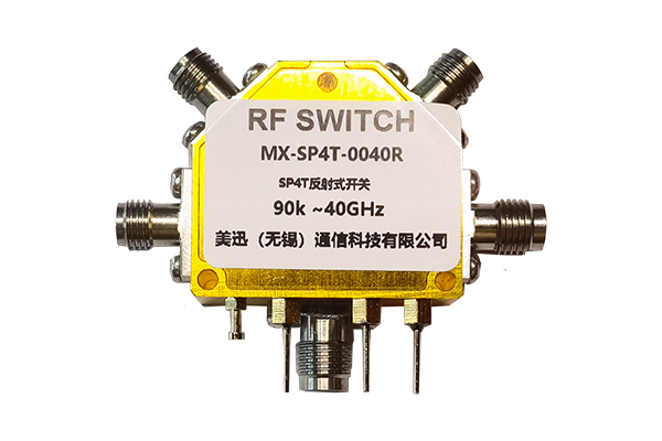
Compare Channels: For multi-position switches, test each port. Single-port failures suggest localized contact/trace issues.
-
Component Swap: Replace the switch with a known-good unit to rule out system design flaws (e.g., mismatched control signals).
-
6 Advanced Diagnosis and Repair
-
X-ray Imaging: Inspect internal soldering/bond wires for cracks/delamination (common in RF MEMS switches).
-
Material Analysis: Use EDX to detect contact corrosion (e.g., silver sulfide buildup).
-
Replacement vs. Repair: Replace for irreparable damage (broken resonators, pitted contacts). Repair for loose screws/worn springs following manufacturer guidelines.


