Insertion Loss of Coaxial Switches
Coaxial Switch Insertion Loss
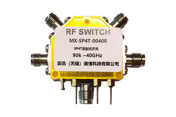
The insertion loss of a coaxial switch refers to the signal power loss that occurs when the RF signal passes through the switch. This parameter is critical in RF and microwave systems, as it directly impacts signal integrity and system performance.
1. Typical Insertion Loss Values
| Switch Type | Frequency Range | Insertion Loss |
|---|---|---|
| General-Purpose | Up to 6 GHz | 0.1 dB to 0.5 dB |
| High-Frequency | Up to 18 GHz | 0.3 dB to 1.0 dB |
| Millimeter-Wave | Up to 40 GHz+ | 1.0 dB to 2.5 dB or higher |
2. Factors Affecting Insertion Loss
- Frequency Range – Loss increases with higher frequencies due to skin effect and dielectric losses.
-
Switch Type –
- Electromechanical Switches: Typically 0.1–0.5 dB (low loss but slower switching)
- Solid-State (PIN Diode) Switches: 0.5–2.0 dB (faster but higher loss)
- Connector Quality – Poorly matched or worn connectors increase loss.
- Impedance Mismatch – A non-50Ω (or 75Ω) system introduces additional reflections.
- Cable & PCB Loss – External wiring can contribute to overall loss.
3. Minimizing Insertion Loss
- Use low-loss dielectric materials (e.g., PTFE) in switch construction.
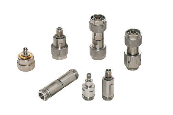
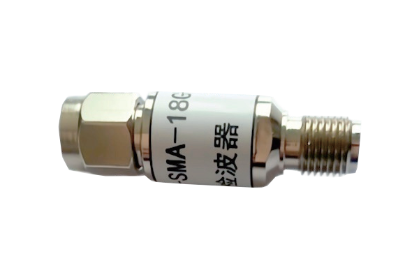
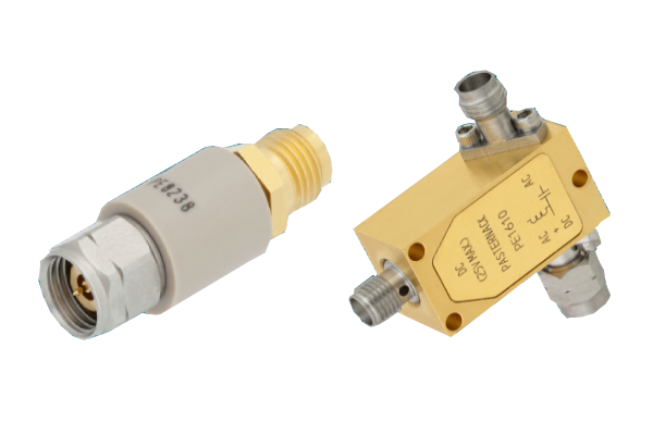
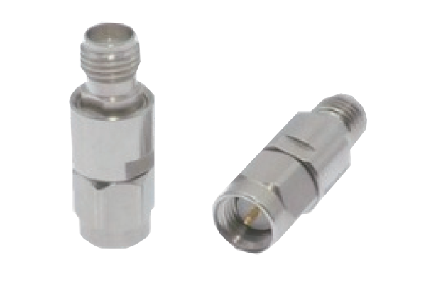
- Ensure high-quality connectors (SMA, N-type, 3.5mm) with proper mating.
- Select appropriate switch technology (electromechanical for low loss, solid-state for speed).
For precise measurements, always refer to the manufacturer's specifications under your operating frequency and power conditions.


