Prepare a vector network analyzer (VNA), a DC power supply, a signal generator, and an oscilloscope. These tools will help measure different aspects of the switch's performance.
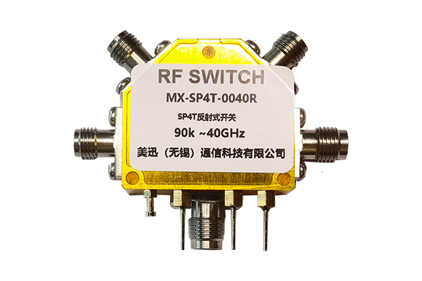
Connect the PIN diode switch to the VNA. Set the VNA to measure the insertion loss over the frequency range of interest. The insertion loss indicates the amount of signal attenuation when the switch is in the "on" state. A lower insertion loss is desirable, typically in the range of a few decibels or less.
With the switch in the "off" state, use the VNA to measure the isolation between the input and output ports. High isolation, usually expressed in decibels, is crucial to prevent unwanted signal leakage. Values of 20 dB or more are often required for good performance.
Connect the switch to a signal generator and an oscilloscope. Apply a square - wave signal to the switch and observe the output on the oscilloscope. Measure the time it takes for the switch to transition from the "off" state to the "on" state and vice versa. The switching time should be as short as possible, typically in the nanosecond to microsecond range, depending on the application.
Gradually increase the power applied to the switch while monitoring its performance. Observe for any signs of distortion, overheating, or failure. The power handling capacity should meet or exceed the requirements of the intended application.
Use a DC power supply to apply different bias voltages to the PIN diode. Measure the current - voltage characteristics to ensure that the diode operates within its specified range and that the switch functions properly under different bias conditions.


