How to test the attenuation value of an RF attenuator
RF Attenuator Testing Procedure
Testing the attenuation value of an RF attenuator requires a systematic approach using specialized equipment to ensure accuracy. Follow this step-by-step guide for reliable measurements:
Setup Preparation
- Gather equipment: RF signal generator, power meter/spectrum analyzer
- Use 50Ω coaxial cables for impedance matching
- Calibrate test setup to eliminate cable/connector losses
- Establish reference power reading (P1) without attenuator
Basic Measurement
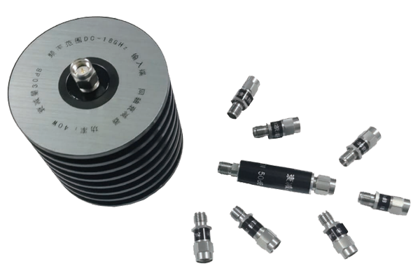
- Insert attenuator between generator and power meter
- Maintain same frequency and power settings
- Record output power (P2) with attenuator
- Calculate attenuation: Attenuation (dB) = P1 - P2
Precision Measurement
- Use vector network analyzer (VNA) for magnitude+phase
- Calibrate with open/short/load standards
- Measure S21 parameter (forward transmission loss)
- This directly indicates attenuation value
Key Considerations
- Ensure impedance matching to prevent reflections
- Minimize cable lengths to reduce signal loss
- Test across rated frequency range for consistency
- Verify linearity at multiple power levels
Application Notes
This testing methodology provides reliable results critical for validating attenuator performance in telecommunications and RF testing applications. For production testing, automate the process using programmable instruments. Always allow equipment to stabilize at room temperature before measurements for optimal accuracy.


