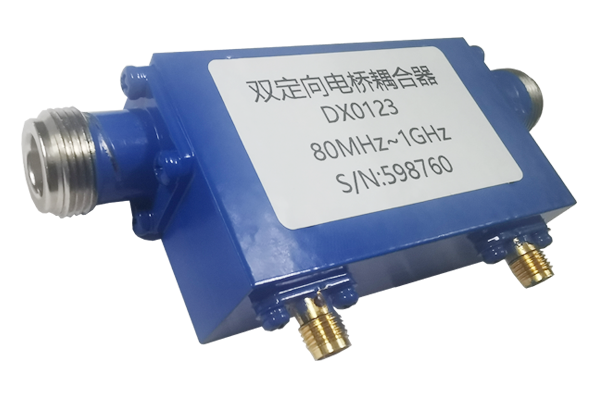
How to Fix Signal Attenuation in a High-Power Coupler
Coupler Signal Attenuation Solutions
Systematic troubleshooting methods to identify and resolve signal loss issues in RF couplers.
Connection Inspection & Maintenance
- Thoroughly examine all input/output ports and coupler connections
- Clean oxidation and debris from contact surfaces
- Ensure all connectors are properly seated and tightened
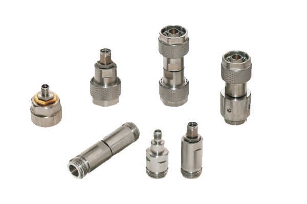
- Replace worn or deformed connectors with compatible replacements
- Verify proper torque on all threaded connections
Internal Component Evaluation
- Inspect internal conductors for breaks using TDR equipment
- Repair broken conductors with precision welding when possible
- Evaluate dielectric materials for aging or cracking
- Replace compromised dielectric components with certified parts
- Verify proper insulation resistance after repairs
Impedance Matching Optimization
- Measure impedance at multiple points using VNA
- Adjust coupler parameters to match system impedance (typically 50Ω)
- Implement matching networks where necessary
- Tune internal structural elements to minimize reflections
- Verify return loss improvements post-optimization
Environmental Controls
- Monitor and maintain operating temperature within specs
- Implement active cooling for high-power applications
- Apply conformal coating for moisture protection
- Use dust seals on all entry points
- Consider environmental enclosures for harsh locations
By systematically addressing these four key areas, technicians can effectively reduce signal attenuation, restore performance, and extend service life of RF couplers in communication systems.


