How are switching speed and response time measured in waveguide switches
Test Setup Components
- Microwave signal source generating stable signals within the switch's operating frequency range
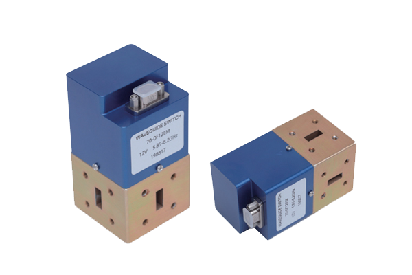
- Waveguide switch under test with appropriate connectors and terminations
- Signal detector (power sensor or spectrum analyzer) to monitor output ports
- Time-measurement device (oscilloscope or time interval counter) synchronized with the control trigger
Response Time Measurement
- Measures the delay from control signal to initial signal transition at output
- Control signal connected to one channel of time-measurement device
- Detector output connected to another channel
- Records time difference between trigger and first detectable signal shift
- Typically uses amplitude threshold (e.g., 10% of full stable value)
Switching Speed Measurement
- Measures full duration of signal transition between states
- Tracks signal from initial change until stable at target level
- Includes rise/fall time and settling time without fluctuations
- For multi-port switches, ensures complete disconnection before new connection
- Prevents signal overlap or dropout in critical applications
Accuracy Considerations
- Calibrate system delays from cables, connectors, and detector response
- Directly connect source to detector to measure inherent time lag
- Precisely synchronize control trigger with measurement device
- Use microwave signals matching switch's rated specifications
- Apply consistent threshold definitions for comparable results
These measurement techniques ensure reliable evaluation of waveguide switches for time-sensitive applications in radar, communications, and test systems.


